

Module 7: Transformer
This module covers the principles, classification, EMF equation, operation, losses, efficiency, voltage regulation, parallel operation, and maintenance of transformers. It also includes sections on small transformer winding and general maintenance of three-phase transformers.
Transformer - Principle - Classification - EMF Equation
Objectives:
- Define a transformer.
- Explain the construction of a two-winding transformer.
- State the reasons for laminated silicon steel being used as core material.
Transformer
A transformer is a static electrical device that transfers electrical energy from one circuit to another without changing the frequency and power. It is crucial for transmitting generated power over considerable distances, allowing for various parts of a power system to operate at different voltage levels. Standard safety norms related to transformers can be found in the International Electrotechnical Commission (IEC - 60076-1).
Two-winding transformers:
A transformer consists of two stationary windings, typically referred to as high voltage (HV) and low voltage (LV) sides. These windings are electrically isolated but magnetically coupled, meaning they link a common flux. The primary winding, connected to an AC source, sets up a periodically varying flux in the core. This changing flux links the secondary winding, inducing a voltage in it by electromagnetic induction. There is no electrical connection between the coils.
Transformers are highly efficient and reliable devices, mainly used to change voltage levels. Their efficiency, typically ranging from 92% to 99% (higher for large power transformers), is due to the absence of rotational losses.
Construction:
There are two basic types of iron-core construction:
- Core type: This involves two separate coils, one on each of the two opposite legs of a rectangular core. This design can lead to large leakage fluxes and poor voltage regulation.
- Shell type: In this construction, the two windings are wound concentrically, with the higher voltage winding on top of the lower voltage winding. The low-voltage winding is closer to the steel for better electrical insulation. This arrangement is preferred for ensuring that most of the flux set by the primary links the secondary.
Cores are typically built from laminated silicon steel sheets. The silicon content (about 3%) in the alloy reduces magnetizing losses, particularly hysteresis loss. Laminations are usually 0.25 to 0.27 mm thick for 50 Hz operation and are coated with varnish or paper for insulation. Coils are pre-wound, and the core design allows for their placement, often requiring the core to be in at least two sections (L and L shaped for core-type, E and I shaped for shell-type).
In larger transformers, a stepped-core arrangement minimizes copper usage and reduces copper loss. Primary and secondary windings often have two or more coils per leg, arranged in series or parallel. Laminations are clamped tightly to prevent fluttering, which can cause objectionable humming noise.
Transformers are usually air-cooled. Larger transformers are placed in tanks filled with special transformer oil, which serves as both an insulating and cooling medium, dissipating heat to the atmosphere or water.
Transformer principle
- Objectives: Upon completion, you should be able to:
- Describe an ideal transformer and its operation on load and no-load.
- Explain the principle of transformer operation.
- Derive the EMF equation of a two-winding transformer.
- Derive the transformation ratio of a transformer.
An ideal transformer:
An ideal transformer has no losses (no ohmic resistance in windings, no magnetic leakage). Its windings are purely inductive and wound on a loss-free core. While not practically realizable, it serves as a basis for analysis.
Working principle:
Transformers operate on the principle of mutual induction based on Faraday's law of electromagnetic induction.
Ideal Transformer on Load:
When a load is connected to the secondary, secondary current flows, causing the primary current to increase. The relationship between primary and secondary currents is based on the comparison of primary and secondary ampere-turns.
On no-load, the primary current (magnetizing current) is small (2% to 5% of full load current) and primarily serves to produce the flux needed to induce an EMF that balances the applied voltage. When a load is connected, the secondary current's demagnetizing effect reduces the flux and induced EMF, causing the primary current to increase to nearly neutralize the secondary's demagnetizing ampere-turns.
Transformation ratio:
The magnetic flux is the link between primary and secondary circuits. Variations in secondary current cause small variations in flux, enabling the primary current to vary proportionally to the secondary current. The no-load current in the primary is primarily magnetizing current, which builds a counter-electromotive force. This alternating current produces an alternating flux, which induces EMFs in both windings.
EMF equation of a transformer:
According to Faraday’s law, the induced EMF ($E$) in a winding is given by $E = N (d\phi/dt)$, where $N$ is the number of turns and $d\phi/dt$ is the rate of change of flux. For sinusoidal flux, the RMS voltage is $E = 4.44 f N \Phi_m$, where $f$ is frequency and $\Phi_m$ is maximum flux.
Therefore:
- $E_1 = 4.44 f N_1 \Phi_m$ (for primary)
- $E_2 = 4.44 f N_2 \Phi_m$ (for secondary)
Voltage Transformation Ratio (K):
$K = E_2 / E_1 = N_2 / N_1$.
This constant varies slightly with load and power factor in practice, but is generally obtained from nameplate data at full load.
- If $N_2 < N_1$ ($K < 1$), it's a step-down transformer.
- If $N_2 > N_1$ ($K > 1$), it's a step-up transformer.
For an ideal transformer, power output equals power input ($P_{in} = P_{out}$), so $V_1I_1 = V_2I_2$, leading to the approximation: $V_2/V_1 = I_1/I_2 = N_2/N_1 = K$.
Rating of transformer
- Objective: Define transformer rating and calculate voltage, current, and turns for primary/secondary windings.
Transformers are rated by their apparent power (Volt-Ampere - VA or KVA), not by true power (Watt or KW). This is because the power factor depends on the load, and rating in KVA allows direct calculation of load current without knowing the power factor. In an ideal transformer, primary KVA equals secondary KVA.
Example 1:
A 100 KVA, 2400/240V, 50 Hz transformer has 300 turns on the secondary winding.
- Given: Transformer rating = 100 KVA, $f$ = 50 Hz, $V_P$ = 2400 V, $V_S$ = 240 V, $N_S$ = 300.
- Calculate:
- Approximate value of primary and secondary currents:
- $I_S$ = 100000 / 240 = 417 A
- $I_P$ = 100000 / 2400 = 41.7 A
- Number of primary turns ($N_P$):
- $V_S/V_P = N_S/N_P \Rightarrow 240/2400 = 300/N_P \Rightarrow 1/10 = 300/N_P \Rightarrow N_P = 3000$ turns
- Maximum flux ($\Phi_m$) in the core:
- $E_P = 4.44 \cdot f \cdot N_P \cdot \Phi_m \Rightarrow 2400 = 4.44 \cdot 50 \cdot 3000 \cdot \Phi_m \Rightarrow \Phi_m = 2400 / (4.44 \cdot 50 \cdot 3000) = 0.0036$ Wb
- Approximate value of primary and secondary currents:
Example 2:
In a transformer, the number of turns per volt ($N/V$) is 8. The primary voltage is 110V. Find the primary and secondary turns of wire if $V_2$ is to be 25 volts.
- Given: $V_1$ = 110V, $N/V$ = 8, $V_2$ = 25V.
- Solution:
- Primary turns ($N_1$): $N_1/V_1 = 8 \Rightarrow N_1 = 8 \cdot 110 = 880$ turns
- Secondary turns ($N_2$): $N_2/V_2 = 8 \Rightarrow N_2 = 8 \cdot 25 = 200$ turns
Classification of transformers
- Objectives:
- State the classification of transformers based on various factors.
- State about dry-type transformers.
1. Classification based on the type of Core Material used:
- Air core transformers: Have a hollow non-magnetic core (paper or plastic). Used in high-frequency applications, they have no iron-loss.
- Iron core transformers: Most common type, used with mains power supply. Have laminated iron cores.
- Ferrite core transformers: Use ferrite material as core. Used in high to very high frequency applications due to minimum losses.
2. Classification based on the shape of core:
- Core type transformers: Primary and secondary windings are on two separate limbs of the core.
- Shell type transformers: Both primary and secondary windings are wound on the same limb of the core. Widely used as voltage and power transformers.
- Ring type transformers: Core is made of circular or semicircular laminations. Disadvantage is difficulty in winding coils. Used as instrument transformers for high voltage and current measurement.
3. Classification based on the Transformation ratio:
- Step-up Transformers: Secondary induced voltage is higher than primary source voltage.
- Step-down Transformers: Secondary induced voltage is lower than primary source voltage.
- Isolation transformers (one-to-one): Secondary induced voltage is the same as the primary source voltage, meaning the number of turns in primary and secondary are equal (turns ratio = 1).
4. Classification based on the operating frequency:
- Mains frequency transformer: Typically iron-core shell type, used as link between AC mains and other devices. Designed for mains supply frequency (50 Hz).
- Audio frequency (AF) transformers: Small in size, often PCB mounted. Operate over 20 Hz to 20 KHz. Used for interstage coupling in amplifiers and connecting amplifiers to speakers.
- High frequency transformers (RFTs and IFTs): Cores made of powdered iron, ferrite, brass, or air. Used for coupling high-frequency circuits. Upper frequency limit is 30 MHz. Often have adjustable cores and capacitors for tuning, hence also called Tuned transformers.
- Very high frequency transformers: Air, ferrite, or brass core material. Specially constructed to minimize losses at very high frequencies. Used in television receivers.
5. Single phase and three phase transformers:
- Single phase transformers: Designed for single-phase AC mains supply.
- Poly-phase transformers (Three phase transformers): Available for three-phase AC mains supply. Used in electrical distribution and industrial applications.
6. Classification based on application:
Transformers can also be classified by specialized applications, including:
- Instrument Transformers: Used in clip-on current meters, overload trip circuits.
- Constant voltage transformers: Provide stabilized voltage supply for sensitive equipment.
- Ignition transformers: Used in automobiles.
- Welding transformers: Used in welding equipment.
- Pulse transformers: Used in electronic circuits.
Dry Type Transformers
Also known as air-cooled transformers, they are commonly used for indoor applications where other transformer types may pose higher risks.
Parts and their functions of transformer
- Objectives:
- List the main parts of a transformer.
- Explain the parts of a distribution transformer.
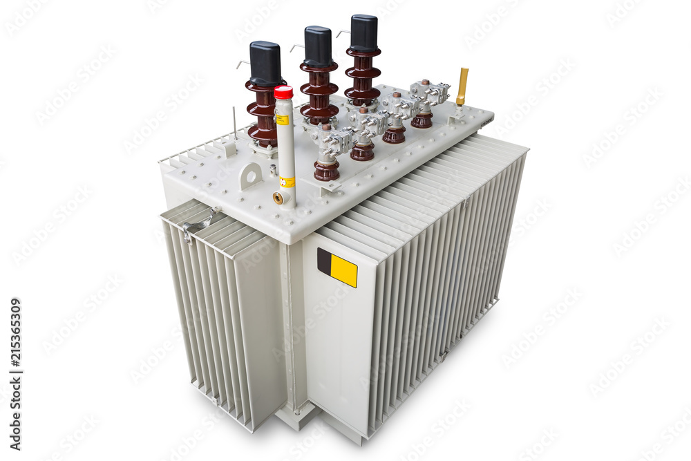
Distribution transformer:
Essential parts include:
- Steel tank: Fabricated M.S. plate tank housing the core, windings, and accessories.
- Conservator tank: Drum-shaped, mounted on top, connected to the main tank by a pipe. Contains transformer oil and an oil level indicator. It accommodates oil expansion and contraction due to temperature changes. A pipe and breather allow air movement to reduce oil oxidation.
- Temperature gauge: Indicates the temperature of the transformer oil.
- Cooling tubes: Dissipate heat generated by iron and copper losses. The insulating oil carries heat from the winding and core to these pipes, where it is radiated to the atmosphere.
- Tap changer: Compensates for voltage drops in transmission lines by increasing sending-end voltage. Taps are typically on the primary winding.
- OFF-LOAD tap changing: Taps are changed manually, requiring the load switch to be opened to avoid heavy sparking.
- ON-LOAD tap changer: Allows tap changing under load. It involves a tap selector switch (selects tap) and a diverter switch (makes/breaks load current). The process involves transferring current through bridging resistors to ensure uninterrupted load supply during tap changes.
- Bushing termination: Insulated conductors (copper or aluminum) passing through metallic sections that are connected to earth, for high voltage power transformers.